

8 Factors That Affect Sulfur Recovery Efficiency in Gas Plants and Refineries
1. Catalyst Deactivation
Catalyst deactivation in sulfur recovery units (SRUs) occurs due to contamination, poisoning, or thermal degradation. Regular monitoring is essential to maintain optimal efficiency and extend the catalyst's lifespan.
2. Inadequate COS and CS2 Hydrolysis
Effective hydrolysis of carbonyl sulfide (COS) and carbon disulfide (CS2) to hydrogen sulfide (H2S) is essential for optimal sulfur recovery. Inadequate hydrolysis can result in reduced conversion rates and increased emissions. Ensuring the optimal operating temperature of converter bed 1 is crucial for efficient hydrolysis reactions.
3. Excessive Converter Dewpoint Margins
Excessive dewpoint margins in converters can lead to sulfur condensation, causing system blockages and reduced efficiency. Maintaining appropriate temperature margins is essential to prevent these issues and ensure smooth operation.
4. Off-Ratio Control (Tail Gas Analyzer)
Maintaining the precise ratio of hydrogen sulfide (H₂S) to sulfur dioxide (SO₂) is crucial. Deviations from this ratio, often managed by a tail gas analyzer, can result in suboptimal conversion of sulfur compounds. Accurate ratio control is essential to prevent efficiency losses in sulfur recovery.
Join Our Upcoming Webinars
5. Inefficient Demister Pad Operation/Sulfur Fog
Demister pads are employed to remove sulfur mist from the gas stream. Inadequate operation or maintenance of these pads can result in sulfur fog and disturbances in operations of the Tail Gas Treatment Unit, thereby reducing overall recovery efficiency. Regular maintenance of demister pads is essential to ensure optimal performance.
6. Elevated Final Condenser Outlet Temperature
The final condenser is crucial for condensing sulfur vapor into liquid sulfur. Elevated outlet temperatures can reduce condensation efficiency, leading to decreased sulfur recovery and increased load on the Tail Gas Treatment Unit. Maintaining optimal condenser temperatures is essential to ensure maximum condensation efficiency.
7. Excessive Turndown
Excessive turndown, or operating the SRU below its designed capacity, can lead to inefficiencies and increased emissions. Operating within the designed capacity range helps maintain optimal recovery efficiency.
8. Routine Operational Upsets
Operational disruptions, such as fluctuations in feed gas composition or unforeseen shutdowns, can significantly impact the sulfur recovery process. Implementing robust control systems and establishing contingency plans are crucial to mitigating the effects of these upsets.
Maximize your sulfur recovery efficiency and ensure operational reliability with Sulfur Recovery Engineering (SRE). Our expert services, including performance evaluation, process optimization, and on-site analysis, are designed to tackle the challenges affecting your sulfur recovery units.
Join Our Upcoming Webinar
The Heat Is On! – Why Temperature Plays an Important Role in Sulfur Recovery

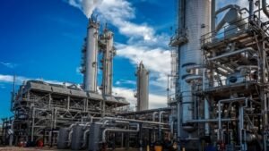
The iconic skyline of Alberta’s natural gas sector is marked by labyrinthine tubes and tunnels, pipes and platforms. Atop it all—like candles on the cakes of carbon—are sputters of live flame, alighting the morning sky.
Far more than just a deterrent to low-flying aircrafts (and birds), the powerful heat of the reaction furnace ensures sulfur extraction is maximized, and the purity of outflow is an optimal makeup for cleanliness and machine reliability.
Too Hot to Handle:

Working with sour water means bringing all the good along with the bad. Side reactions inside the reaction furnace will invariably produce unwanted products like CO, H2, COS, and CS2. Luckily, other contaminants such as BTEX, Mercaptans, NH3, HCN, Methanol, and HCs may be destroyed in the reaction furnace with proper calibration and sufficient heat.
While 900℃ (1650℉) is the minimum temperature for flame stability, heats of 1050℃ (1920℉) or above are capable of destroying the unwanted contaminants. Bear in mind the reaction furnace is kinetically limited based on residence time, turbulence, and temperature, as well as burner efficiency.
Through the Fire and Flames:

In our Sulfur Recovery experience, combustion air flow rates are nearly always off by at least 10–20%. While this is standard, we must work to ensure this margin of possible error is not exacerbated. Proper mixture of gasses and the installation of a high-efficiency burner can increase reaction furnace temperatures up to 100℃, which helps to reach the target temperatures mentioned previously.
This is crucial not only for efficiency, but for optimal refinery health. Proper burn-off of ammonia in the reaction furnace is essential, as residuals can carry over to the condensers and converters, bringing with them the risk of forming ammonia salts. These salts will negatively impact heat transfer and recovery efficiency. As with most sulfur recovery unit issues, you won’t know there is a problem until it is too late.

As with any efficient furnace system, management of both inflow and output should be carefully monitored, with changes to procedure made according to the changes in both. Ensure your plant is optimized for the feed it receives. For example, when H2S qualities are low in gas plants, a front side split configuration is often best for ensuring minimal additions of air and nitrogen to the system.
Conclusion:
Sulfur recovery isn’t always easy, but it is undoubtedly important. In the end, you should run your reaction furnace like you would your bathtub: the hotter, the better; the better, the cleaner! Learn more about how we can help you optimize your Sulfur Recovery by contacting us at our website, subscribing to our newsletter, or by giving us a call today.
Ammonia Analysis – SRU Protection
SRE is the only firm in the Oil & Gas industry that can provide timely, on-site results with respect to ‘bulk’ and ‘trace’ ammonia testing. In addition to our standard ‘bulk’ ammonia analysis of refinery-based sour water stripper (SWS) acid gas feed streams, we are capable of measuring the ammonia content (i.e. ppm level) in amine acid gas and the stream exiting your reaction furnace (RF). These specialized services are another example of SRE’s commitment to the efficient and long-term operation of our clients’ SRUs by way of research and development.

Based on 20+ years of field-testing experience, SRE strongly recommends ammonia breakthrough from the RF is kept below 150 ppm. The prevention of ammonia salt formation in downstream condensers will ensure optimal sulfur recoveries are realized without capacity reduction, all while preventing costly shutdowns to unplug or replace condenser tubes. While on-site, SRE Engineers will work with operations to maximize ammonia destruction by way of optimizing your front-side split parameters and, if applicable, adjusting the fuel gas co-firing strategy.
The combination of an SRU performance test and ammonia destruction study will minimize the potential risk of downstream ammonia salt formation in your SRU. SRE’s specialized services are designed to protect your facilities, personnel, and bottom line.
Breakdown: Claus Processing Units
Today we will be breaking down the different components of Claus Processing Units. Let’s take a look at each component and some best practices to guide you as you consider your own operations.

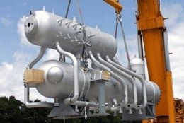
Reaction Furnace
This is the first unit in the Sulfur Recovery Unit (SRU) process where feed enters and where thermal combustion happens. Most of the heat is produced in this section due to the highly exothermic reaction (H2S is burned using oxygen to produce desired amount of SO2). The inner walls of the reaction furnace are lined with refractory bricks to protect the shell of the vessel from the extreme heat.
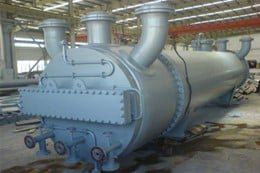
Wasteheat Boilers
The wasteheat boiler is attached to the back of the reaction furnace. This is where most of the heat removal takes place. These boilers are available in either a one-pass or two-pass design. A two-pass is used when there is a hot gas bypass already in place. By sending hot, processed gas to the first converter, the tube sheet is protected from high temperatures and sulphite attacks. When it comes to removing heat, the waste heat boiler is your friend— just let that hot steam rise to the top!
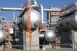
Claus Process Condenser
The Claus process condenser is an excellent shell and tube heat exchanger. Its function is to remove sulfur and heat. It separates gas and the liquid leads into your liquid-sulfur run downs. It maintains an outwards temperature in the range of 150°C to 165°C to minimize the sulfur vapour carry-over to the incinerator. Any higher than that and things might get frenetic! Keep in mind that condensers achieve low pressure steam production — 50 psig. Use this steam in heat tracing, as desired. That steam is produced on the shell side, with sulfur product on the tube side.

Reheater
Reheaters play a crucial role in maintaining sulfur temperature and avoiding condensation in the converters. Remember that processed gas leaves the condenser at the sulfur dew point temperature. This temperature must be increased. This increase provides optimal temperature for the Claus reaction in the gas phase and on to the converters.
Although two reheating methods exist, one is clearly superior. The direct reheating method is less desirable, as it adds additional sulfur bearing compounds to the process; this immediately lowers the overall practicable efficiency of the SRU. Moreover, between 0.1-0.5 % loss of sulfur can occur through this method.
Indirect heating is preferred for this reason. Harnessing the mighty power of steam, no added compounds can crawl through the pipes and into your end product. Simple to control and with no effect on overall practicable efficiency, indirect heating is the industry gold standard. Cost issues may arise, however, as some refineries see steam costing up to $5 per ton. The key point here is to focus on maintaining a 2:1 H2S to SO2 ratio.
Whatever the method, once converted and reheated the sulfur moves to the catalytic converter stage and incineration stage.
Catalytic Converter , Thermal Incinerators and Instrumentation
The catalytic reaction occurs at this stage. Through an exothermic reaction, heat is released, and the temperature begins to rise in the catalyst bed. Temperature control, as always, remains critical. Here, Claus reaction is favoured at lower temperatures. We want the processed gas to be in the gas phase.
Once catalyzed the thermal incinerator comes into play by converting the remaining off gas into SO2. The temperature of your incinerator should not exceed 650°C. Keep in mind that this is controlled by the amount of fuel gas and air being burned. Be sure to monitor SO2 concentrations at ground level for proper plume dispersion. Instrumentation can help monitor oxygen levels within a 2-4% range, but they are not always accurate. Make sure you understand the normal base conditions to avoid excess temperatures and any accidents.
We hope this blog was informative to you and your Claus Processing Unit aspirations. Follow our blog for more pertinent and useful updates in the field of sulfur recovery.
The Importance of High Quality SRU Feed Streams
The SRU is only as good as the feed streams it receives – this is a common statement in the sulfur recovery industry. Before testing

The SRU is only as good as the feed streams it receives – this is a common statement in the sulfur recovery industry. Before testing an SRU, one of the first questions we ask is “how stable is the acid gas flow”? And after analyzing the samples, one of the first things we check is the acid gas quality, i.e., the H2S content, as well as the concentrations of contaminants in the feed stream(s).
The reaction furnace (RF) is the first vessel and considered the ‘heart’ of the SRU. Its performance is based largely on the quality of feed stream(s) it is processing, whether it be only Amine Acid Gas (AAG), or the additional Sour Water Stripper Acid Gas (SWS AG) often processed in refineries. The H2S content affects how hot the RF can run, and the higher the better; it also dictates which configuration can be utilized, whether it be straight through, split-flow, or direct oxidization.
The concentrations of contaminants, mainly hydrocarbons and BTEX, is also important for the RF performance. For their complete oxidization, hydrocarbons require much more oxygen than H2S does; this negatively impacts the smooth operation of the Air Demand signal. Hydrocarbons and BTEX also cause various issues downstream if they are not completely oxidized, therefore keeping their levels at a minimum is vital. Maintaining stable and consistent feed stream flows is also crucial for the smooth operation of the Air Demand control loop.
Optimizing the operation of upstream Amine and Sour Water units is vital for providing the SRU with the highest possible quality feed streams, and for minimizing the levels of contaminants. SRE now offers full Amine Unit Performance Evaluations, along with the SRU testing we’re known for. Our highly trained team of engineers can safely obtain these hazardous samples, and our optimization programs make the sour units achieve the highest efficiencies they were designed for.
Hydrocarbon Present in Amine Solvent Downstream of Absorber
Problem Definition A South American Refinery Client requested assistance tackling the problem of hydrocarbon being present in their amine solvent (rich amine). The client reported
Problem Definition
A South American Refinery Client requested assistance tackling the problem of hydrocarbon being present in their amine solvent (rich amine). The client reported an incidence of hydrocarbon in their acid gas stream going to SRU. They are looking into putting a flash tank in service for the amine circuit and require SRE’s analysis to determine prime location, operation guidelines, and instrumentation required. There was an existing flash tank and was put out of service long ago, the tank was designed as a charge drum for amine system. P&ID of the amine circuit was provided (flash tank situated after the lean-rich amine heat exchanger) along with their current option.
SRE’s Response
Within a couple of days of receiving the request, SRE reviewed the P&ID and information provided by the client to present the recommendations. Flash drum should be installed after the absorber, and before the lean-rich amine heat-exchanger, to ensure Hydrocarbon is condensed and a significant amount of H₂S is NOT flashed. As per industry practice, absorbers operating below 10 bar usually do not require a flash drum. It was advised to the client to further investigate the event of hydrocarbon carryover to ensure there is no permanent damage to the amine circuit/equipment.
A write-up was sent to the client explaining where the flash drum should be installed and what the limitations will be. In addition, operation guidelines and instrumentation requirements were also presented to the client. For the short term, the client was advised to ensure that the amine inlet separator is functioning well, and that extra precautions are taken to stop hydrocarbon from entering the amine circuit.
RESULTS
The client was fully onboarded with SRE’s recommendations. They will strive to ensure that the flash drum will be installed upstream of lean-rich amine heat-exchanger and that proper instrumentation will be used. Operation guidelines have been provided to the client and will be further refined as the need arises.
SRE continues to provide support to this client as they are in the process of the modifications.

Solids Contamination
Problem Definition European Refinery Client requested assistance with solids contamination in their DEA system. Corrosion issues in the regenerator bottom section and reboiler were reported.
Problem Definition
European Refinery Client requested assistance with solids contamination in their DEA system. Corrosion issues in the regenerator bottom section and reboiler were reported. Amine analysis results were sent to SRE for review.
SRE’s Response – Solids contamination
Within one hour of receiving the request, SRE provided review of DEA analysis results and reported to the client that Heat Stable Amine Salt (HSAS) levels were considerably higher than maximum guideline level of 2 weight percent and were the probable cause of corrosion in the regenerator and reboiler.
The contamination in the system was the result of high corrosion rates found in the unit. A report on HSAS management was sent to the client. Additional guidance was provided to the client on short-term mitigation of HSAS using neutralization to immediately reduce the corrosion problem.
RESULTS
Using SRE’s guidelines, the client was able to reduce HSAS to an acceptable level. Solids contamination and corrosion rates were reduced.
SRE continues to provide assistance to this client to maintain the unit within guidelines for HSAS, solids and corrosion.

Sulfur Pit Degassing
Why do we degas? Crude oil and natural gas contain sulfur compounds which get concentrated as they makes their way to the SRU in the
Why do we degas? Crude oil and natural gas contain sulfur compounds which get concentrated as they makes their way to the SRU in the form of hydrogen sulfide (H2S). H2S is present in liquid sulfur in two forms: dissolved and chemically bound (known as polysulfides or H2Sx). The residual H2S content in produced liquid sulfur can be in excess of 600 ppm and the Lower Explosive Limit (LEL) for H2S in air is 4% which is easily reached if liquid sulfur is not degassed. The main goal then of degassing is to reduce the potential safety risk to people, the environment, and equipment. Increasing product purity may also be a reason for degassing to lower levels. The industry standard for safe handling of sulfur product is 10 ppm or less.
Degassing typically consists of two stages, an agitation stage followed by a sweeping stage. Air is typically used in both stages as it is readily available and cheap, oxygen also promotes the direct oxidation of hydrogen sulfide and polysulfides. That being said, other gasses such as nitrogen, steam, and Claus tail gasses can also be used for sweeping the released H2S from the pit.
There are several processes that can be seen in industry and that have been implemented around the world. It is likely that if you have worked in a sulfur plant that you have experience with one or more of these processes.
Comprimo (Formerly Exxon) Degassing Process
Air used for sparging and sweeping
Catalyst added to pit to promote decomposition of polysulfides
Aquisulf (SNEA)
Aquisulf catalyst
Multiple compartments
Shell
Uses air for agitation
Stripping column within the pit
Enersul HySPEC
Series of CSTRs (Continuous Stirred Tank Reactors)
Air used to sweep and catalyst added
Fluor D’GAASS
Pressurized above-ground contactor
Air used for agitation
CSI ICOn
Fixed catalyst bed contactor before or after pit
Operates at pressure of SRU
Finally, we’ll talk about operation and troubleshooting fundamentals. Knowing the basics of degassing chemistry, such as the kinetics, effects of catalyst, and flow characteristics provide a solid foundation for any issues that you may encounter. The next step is knowing your design, understanding how your particular process works compared to others is necessary to being able to identify problem areas. Lastly, ensure that your data is accurate and reliable when monitoring KPIs. To help with this, get onsite verification of your process, including fact checks of technical drawings and data, and liquid sulfur testing.
Reach out to us at SRE for more information on troubleshooting tips and support as well as some interesting case studies from our experience.
IMPROVE SAFETY, INCREASE RELIABILITY, & REDUCE COSTS

Traditional vs. Above Ground Sulfur Seal Legs
While catalytic converters perform the sulfur conversion portion of the modified Claus unit, sulfur condensers allow for the recovery of that sulfur in a liquid state.
While catalytic converters perform the sulfur conversion portion of the modified Claus unit, sulfur condensers allow for the recovery of that sulfur in a liquid state. After the sulfur is condensed from a vapor to a liquid, it drains through a gravity rundown system into the temporary sulfur storage pit, or collection vessel. At the beginning of the sulfur rundown system, the liquid side must be sealed off from the vapor side to prevent process gas from escaping with the liquid sulfur. The two types of sulfur sealing mechanisms are the traditional underground seal leg, and the increasingly common above-ground sulfur seal. Both types have their strengths and weaknesses.
The traditional underground (in-ground) sulfur seal leg has been used in SRUs for over 50 years. These depend on the head pressure of a liquid sulfur level within the vertical leg to act as a vapor seal and block the process gas. Traditional seal legs function well during normal operation, but in the event of a pressure spike they may cause process gas to blow out and into sulfur storage. While supplemental gas relief can sometimes be desirable, this gas contains hazardous H2S and SO2, and will continue to enter the sulfur pit until the leg is refilled with liquid sulfur. In addition to this, underground seal legs are also cumbersome to remove in the event of plugging off.
Above ground sulfur seals have been around since the 1990s, they utilize a float and orifice to create a vapor seal, similar to a float steam trap. These seals do not allow process gas to enter sulfur storage, because any pressure event will immediately close off the orifice. There is, therefore, no supplemental relief path in these original above-ground designs. While being much easier for maintenance and accessibility, the original design does require periodic cleaning of the filter screen. CSI has, however, developed an advanced version of the above-ground seal which addresses the perceived weaknesses of the original design, called the SxSealTM 2000. This sulfur seal has been very well received and allows for both supplemental pressure relief and simple clean-out without having to open it up and remove a screen. While some companies can be reluctant to deviate from traditional methods, advancing technology will always provide means of improvement, thereby reducing safety hazards and increasing operational effectiveness and ease-of-use.

Trace Oxygen in Raw Gas To Determine Corrosion Source
Q4 2017 saw SRE complete a number of interesting projects. For one gas plant in Canada, SRE was involved with determining the source of corrosion with our client’s gas sweetening unit.
Q4 2017 saw SRE complete a number of interesting projects. For one gas plant in Canada, SRE was involved with determining the source of corrosion with our client’s gas sweetening unit. In an amine system, corrosion problems can easily be identified by the color of the amine: pale green indicating light corrosion; brown indicating corrosion greater than the filtration capabilities; and black indicating dangerous levels. Although there are many sources for corrosion, our client had already identified that their corrosion was most likely cause by an increased amount of Bicine.
There are several mechanisms for producing bicine in amine gas treating facilities which include (1) reaction of diethanolamine (DEA) with glyoxal – a common hydrogen sulfide (H2S) scavenger – and (2) exposure of the heated gas treating solution to an oxidizer. Bicine impacts gas treating amine solutions in two ways. First, it forms heat stable amine salts (HSAS) and second, it increases the corrosivity of the amine solution. Here, it was thought that the oxidizer was Oxygen (O2) ingress from the field raw gas.
As such, SRE’s scope of work was to complete trace O2 analyses at various points through the gas plant, including the raw gas from each field and throughout the inlet lines to the Amine contactors. In one day, SRE conducted 22 trace O2 measurements from 10 different locations. Sampling was extensive as a 3-minutes sample time and portable equipment allowed the site Engineer to be able to request extra measurements for due diligence. These capabilities are in stark contrast to a trailer full of equipment and a 2-hour run time – 1 hour to mobilize, 30 minutes to warm up line and 30 minutes to conduct analysis – used by other testing companies, where 22 samples could take a few days & cost 3 times more.
Results ranged from 20 ppm to 250 ppm with all raw gas inlets having a measurable amount of O2. The site Engineer planned to use the data to conduct their own material balance and to continue to mitigate the amine system corrosion.